LENGTH MATCHING ROUTES
Introduction
Length matching or net tuning is often used with higher speed or longer distance signal runs on the PCB to improve signal timing or signal integrity. The basic idea is that the shorter trace follows a detour or meander in order to lengthen it to match the length of the longer trace.
Length matching and net tuning are part of the Advanced Feature Set, available from PCB Level 2 onwards.
The commands described in this topic are gathered into a High Speed Design submenu on the track context menu. Right click on a selected route and the submenu offers Match route lengths, Input target length, Remove length matching, Tag length matches, Reverse route direction and Configure length matching, together with the differential pair commands Phase-match diff. pair, Display phase-offset and Remove phase-match serp.
Matchgroups
After traces have been matched in length they belong to a matchgroup. A matchgroup is simply a container for a set of routes that have been successfully length matched. It includes the target length, the tolerance, the serpentine configuration and a list of the routes that belong to it. You can have as many matchgroups as you need in a design, each with different serpentine configurations and tolerances; Proteus will take care of managing and storing the configuration for each matchgroup.
Matchgroups are internal data structures with no direct user interface but you can browse and select them via context menu commands.
Background Rationale
High speed digital interfaces transmit data as edge transitions rather than static voltages. To ensure reliable sampling, related signals must arrive within a very tight time window. Any difference in arrival time between members of a group is called skew.
In PCB material such as FR-4, signals travel at roughly 150–170 picoseconds per inch (about 6–7 ps per millimetre). This means that even a few millimetres of extra trace length can create tens of picoseconds of skew. At multi-gigabit data rates, these delays are large enough to cause setup or hold violations.
Industry standards therefore specify skew budgets:
-
DDR4 typically allows ±25 ps mismatch between a strobe (DQS) and its associated data lines (DQ).
-
PCI Express and similar serial buses tolerate only a few millimetres of length difference between lanes.
-
HDMI and USB also define differential and group matching requirements to maintain eye openings.
Length matching tools in Proteus provide a way to meet these requirements by tuning trace lengths until all members of a matchgroup fall within a defined tolerance. Serpentine routing segments are added automatically or interactively adjusted to achieve compliance. This workflow follows the matched length practice recommended for high speed packaging in IPC-2251; the tolerance itself comes from the interface's timing budget, as in the examples above.
Length Matching tracks to each other
Normal Track Matching
Here we are looking at matching the lengths of tracks that are not part of a differential pair.
1) Configure the length tuning options from the Set Length Tuning dialogue, which is opened with the Technology Menu > Configure Length Matching command. The same dialogue is also available from the track context menu at High Speed Design > Configure length matching, so you can reach it without leaving the route you are working on. Configuration of various options depends on signal speed and designer priorities but at a minimum make sure that the length tolerance is suitable.
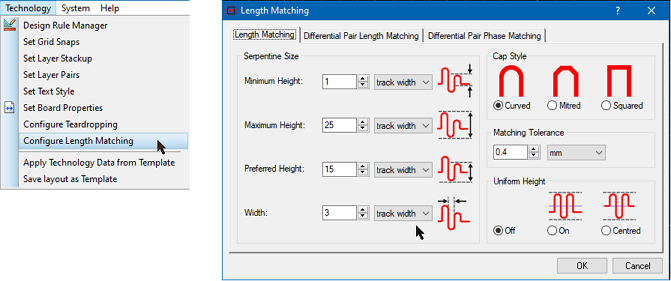
The Length Matching tab of the Set Length Tuning dialogue.
You'll find a lot more information on the various configuration options by clicking on the question mark (?) to access the dialogue level help.
The Uniform Height control has three settings: Off, Centred and On. We do not recommend Centred or On unless you have no choice. Forcing the serpentines to a single height severely constrains the algorithm and is likely to result in failure to complete where space on the PCB is limited.
2) Hold the CTRL button down and successively left click on the two routes such that both are highlighted. Right click on one of the tracks and select High Speed Design > Match route lengths from the resulting context menu.

Select both routes, then invoke Match route lengths from the High Speed Design submenu.
3) A successful match will be indicated, together with the actual delta between the traces on the status bar.

The status bar confirms the match and reports the maximum remaining difference.
Length matching in Proteus takes place from designated connection point to designated connection point (in other words centre pad to centre pad). Since the route of the signal from the connection point on the PCB to the component is unknown the earliest available point at which to start length matching is the centre of the pad.
You can add tracks to a group of already length matched tracks by including one of the already matched tracks in the length match operation. Similarly, you can remove individual tracks from a matchgroup with the Remove length matching command on the same High Speed Design submenu.
Once a matchgroup has been formed Proteus will attempt to maintain it after edits. So, if you edit one track it will automatically re-match (space permitting) the other tracks to keep all the lengths within tolerance. Length matched tracks will not be disturbed by normal push mode routing (cannot be pushed) so this refers to deliberate manual editing of a track in a matchgroup.
See Also:
Differential Pair Length Matching
It's important to understand that we're not matching the length of one track in the differential pair to the length of the other track in the differential pair. This is done automatically by differential pair phase matching. What we are doing here is matching the length of one differential pair to the length of another differential pair.
Start in the same way as before by configuring the length match options with the Technology Menu > Configure Length Matching command. This time we want to switch to the Differential Pair Length Matching tab of the dialogue.
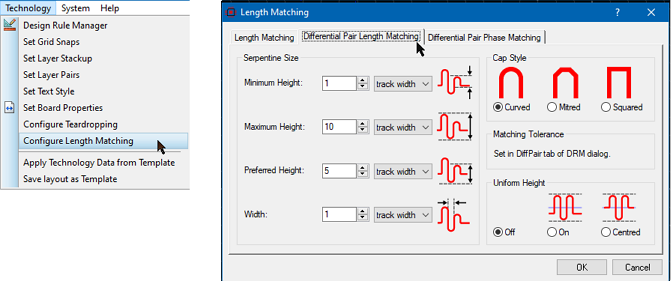
The Differential Pair Length Matching tab of the Set Length Tuning dialogue.
This dialogue allows you to control the topology of the differential pair length matching. Since tolerances are typically part of the protocol specification you'll set them separately in the Differential Pairs tab of the Design Rule Manager. As an example here we might typically set the serpentine sizes to be multiples of the separation between the two diff pair tracks and opt for mitred cap styles.
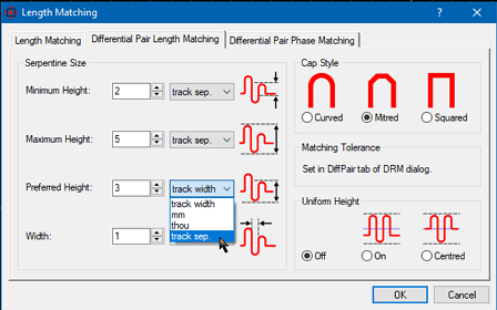
Set the serpentine topology for the pair, here as multiples of the track separation with mitred caps.
Now we follow the same process as for normal length matching. Hold the CTRL button down and successively left click on one route in diff pair number 1 and then a route on diff pair number 2 such that both are highlighted. Then right click on one of the tracks and select High Speed Design > Match route lengths from the resulting context menu.
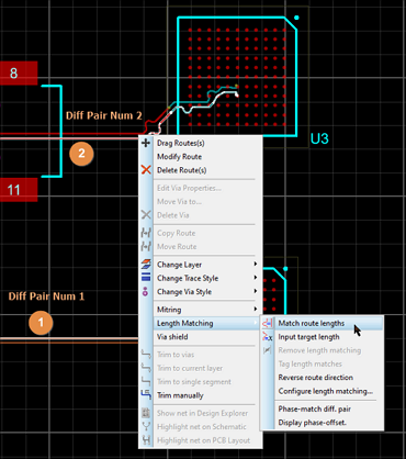
Select one track on each differential pair before matching the lengths.
The shorter differential pair will then serpentine according to the specified topology in order to match length with the longer pair.
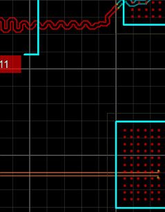
Matched Diff Pairs
Note: Length matching serpentines will add corners which can change the lengths of the two tracks in the differential pair with respect to each other at a given point on the route. A phase matching pass is done after the length matching is completed but in turn it's possible that this adds length to the pair. It's important therefore to know what the phase matching tolerance (sometimes called skew) and the length matching tolerance are for your signal speeds and to set the parameters correctly in the design rule manager. More information can be found in the section on phase matching. The phase matching visualiser is also a really useful tool in showing you the phase status across the entire route.
Length Matching tracks to a specific value
Instead of matching the length of the tracks with respect the longest track in the selection you can choose to match the length of the tracks to an absolute value with the Input target length command on the High Speed Design submenu.
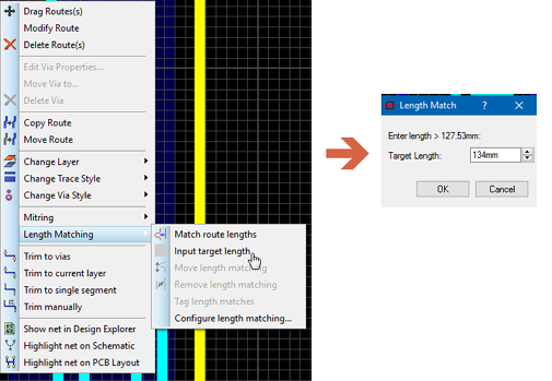
Enter the target length for the selected routes.
The original length of the longest selected track is shown above the edit box. The target length you enter must be longer than this otherwise the operation will fail.
You can do exactly the same with a differential pair by right clicking on either track on the differential pair (no need to highlight them both) and entering the target length as shown above.
Removing Length Matches
To remove a serpentine from a track simply select it and use the High Speed Design > Remove length matching command on the track context menu.
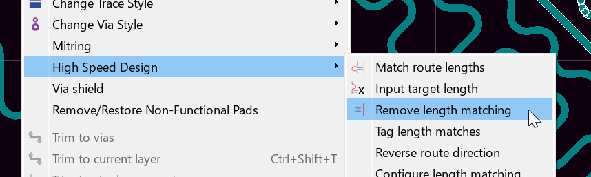
Remove length matching from the selected route.
This will work for several tracks as well: simply hold CTRL down, left click the tracks you want and then invoke Remove length matching from the context menu.
If you remove the longest track from the matchgroup (the target track) then the track will be removed from the group and the rest of the matchgroup will regenerate with the next longest track as the target length for the group.
Moving Serpentines on the Route
To move the serpentine to a different section of the route simply left click to select and then drag with the left mouse button.
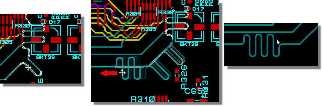
Moving a Serpentine section to a different place on the route
Notes:
- When matching a lot of routes in a tight space it is often best to match a few routes and then move the serpentines manually to create the most space for matching the remaining routes.
- You cannot move a serpentine onto a segment of route that is part of another matchgroup. This often happens with daisy chain topologies where one segment of track is part of multiple matchgroups.
Pin-Pin Matching
Length matching in Proteus currently works on a pin-pin basis. If vias are used then the length of the via is determined from the layer stack information. Micro-via spans are handled in exactly the same way, so a laser-drilled span contributes only the depth it actually traverses rather than the full board thickness. You cannot length match through a tertiary junction because the meaning is ambiguous, since it is not clear which route is being matched.
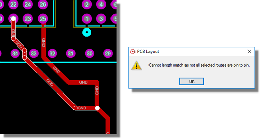
Length matching is refused where the selection is not an unambiguous pin to pin route.
Complex Length Matching
It is sometimes unavoidable that one section of track belongs to more than one matchgroup. A good example of this is the fly-by routing of the CMD/ADDR lines with DDR3. As an example, consider the following topology.
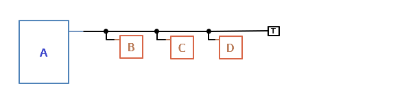
Simplified fly-by configuration example.
AB, AC and AD are all critical signals and will need to be matched to specific lengths. It is inevitable however that some track segments will be included in multiple matchgroups.
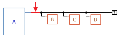
This section of track is an example of one which will be included in several matchgroups
There are two important points to remember when length matching something like this:
Selection
The user needs to help the software by limiting the selection to an individual, pin-to-pin, route. In a complex configuration, this means holding the CTRL button down and left clicking on track segments to tag only the full route that you want to match. The route must start at a component pad and must finish at a component pad.
In our simple example, you would first select the track from A to B through the via.
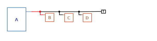
Select the full pin-pin route from A to B
In Proteus, this is done by left clicking on one segment of track (Eg. pin to via) and then holding down the CTRL key and left clicking again to highlight the second segment of track (e.g. via to pin.)

Use the CTRL key to select stub lengths of track and ensure that you have the full correct route tagged.
Once the route is selected, we can right click and use High Speed Design > Input target length to set the length for the route.
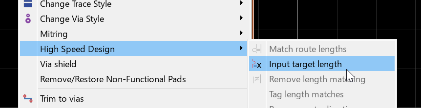
Set the target length for the selected pin to pin route.
Distance travelled through the via is taken from the values specified for layer thicknesses in the layer stackup (Technology Menu).
Next, we would select the track from A to C through the via.
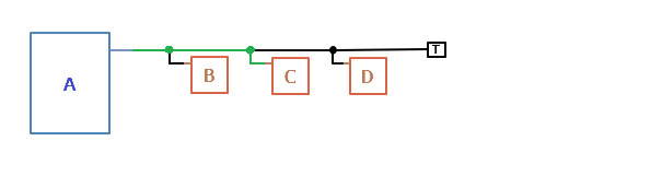
Select the full pin-pin route from A to C (note the stub to B is not tagged)
Again, in Proteus we select the first track and then hold the CTRL button down and left click to select the second track to tag the entire pin to pin route.

Make sure that you tag only the desired signal route before length matching.
We input the target length for this route and then continue with exactly the same process for route AD.
Ordering
The example we have used is one in which the order of length matching is important. The user should first match AB to its required length as shown below. Since AB has less space to serpentine it is more likely to require the common trace section for lengthening.
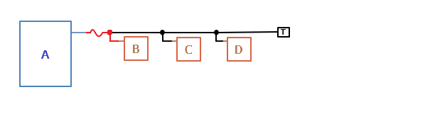
First, set the target length for AB.
Once a trace section belongs to a matchgroup it cannot have it's length changed when it is included in another matchgroup. The setting of target length for AC can therefore only change the length of the trace segments to the right of the first via.
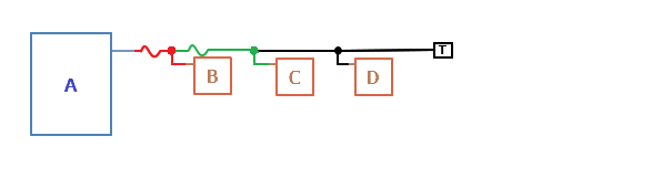
Only the green sections are available for serpentines in order to achieve the target length for AC.
Our final action is then to set the target length and length match route AD.
Summary
- Make sure to select a complete and un-ambiguous route from source pad to destination pad.
- Where multiple length match operations will share some track segments, start with the route containing the shortest length of common track and work upwards to the longest one.
Adding Internal Lengths
With Proteus, you can easily add internal lengths to footprints on the layout. This enables more accurate matching for critical signals, particularly with BGAs where the signal delay inside the chip can be relevant.
Internal lengths are created as a simple CSV file of the format
<pin name>, <internal length>,
where the internal length data is sourced from the manufacturer's toolsuite. This is applied to the part on the layout with the Add Internal Lengths command on the pad context menu.
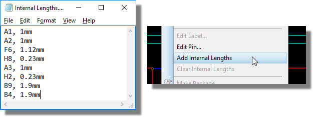
Internal lengths are supplied as a comma separated list of pin name and internal length.
Length matching will then include internal distances when matching. When you select a route the status bar reports the etched length and the total length separately, the total being the etched length plus the internal lengths at each end. The length match report gives the total length for each route together with the internal length of each of the two pins, so the etched figure can be derived from it.

The status bar reports the etched and the total length of the selected route.
If you are using software such as TimingQuest and you know of a format that can be exported and contains this information (pin name, internal length) then please let us know as we may be able to import it directly. ([email protected])
Viewing and Browsing Matchgroups
You can browse and tag all length matched nets and routes by selecting connectivity highlight mode and changing the filter in the Object Selector to Length Matched.
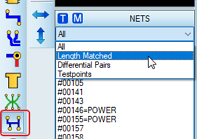
Change the Object Selector filter to Length Matched.
This restricts the Object Selector to length matched routes only.
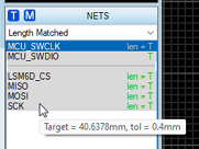
The Object Selector filtered to length matched routes and grouped by matchgroup.
The list is grouped by matchgroup and the right hand side shows compliance with the target length. Hovering over an item provides tooltip information on the target length and the tolerance for the matchgroup. Where a set of tracks are matched to a target length the right hand side will compare the length to the target (e.g. len=T). Where tracks are just length matched to each other one of the tracks (the longest one) will be the target and so simply say T on the right hand side.
Members of a matchgroup that are non compliant will show in red whether they are greater than or less than the target length.

A non-compliant route is shown in red with the amount by which it misses the target.
When you double click on an entry you'll tag the route in question. Alternatively, use the T button (Tag Instances) at the top of the Object Selector to select the current route.
The M button (Tag Length-matched routes) at the top of the Object Selector will tag the entire matchgroup that the currently selected route is part of. Similarly, when you right click on an entry and select Tag Length-matched routes then all matched tracks on the net will be tagged on the PCB.
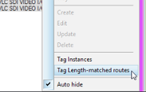
Tag Length-matched routes on the Object Selector context menu tags every matched route on the net.
These are often but not always the same thing. It is quite possible to have a net on which some routes are length matched and others are not.
Pre-Production Check
The target length for a matchgroup is stored with the matchgroup and the pre-production check will test against this length prior to board manufacture to double check that no track nudging has taken place.

The pre-production check reports any length matched route that has drifted out of tolerance.
Length Match Reporting
To generate a length match report open the Project Notes module and select the length match template.
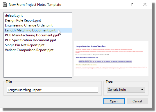
Select the length match template in Project Notes.
Alternatively, if Project Notes is already open you can select a new note from the File menu. The module needs to be unlocked to enable the new note command.
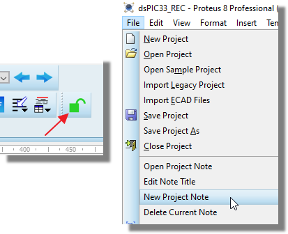
Create a new note from the File menu in Project Notes.
The report has nine columns: Match Group, Net, Pin1, Pin2, Pin1 Int. Length, Pin2 Int. Length, Total Length, Target Length and Tolerance. Rows are grouped by match group, and each row names the net and the two pads at the ends of the route. The Tolerance cell carries a tick or a cross alongside the tolerance value, indicating whether that route is inside the tolerance for its match group.
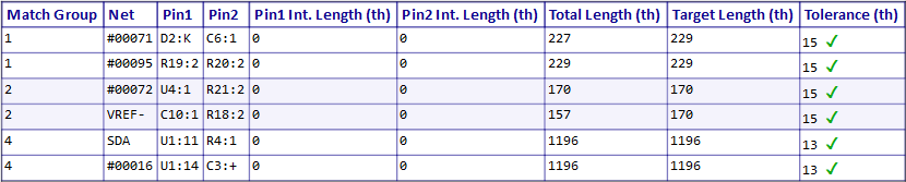
The length match report table, grouped by match group.
If you make changes on the layout (e.g. to correct a non-compliant route) you can reload the report from the right click context menu.
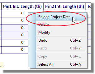
Reload the project data to refresh the report after editing the layout.
Like all Project Notes reports you can save out as PDF or simply store with the Proteus project. The report is timestamped to indicate the last time it was re-generated.
The same process can be followed with the dedicated differential pair report to produce detailed information on differential pair length matching.